
Products
Before we dive into our real-world project, it's crucial to establish a solid understanding of the foundational concepts of TinyML.
I want to clarify that this project will utilize existing datasets, Google Colab, and Arduino code created by Pete Warden and the TinyML team at Harvard University. Their resources will support our deployment on a microcontroller unit (MCU) by providing:
· Access to datasets
· Model architectures
· Training scripts
· Quantization scripts
· Evaluation tools
· Arduino code
Please note that we do not own most of this code, and this project assumes a basic understanding of programming and electronics.
In this project, we will create a simple robotic subsystem that employs machine learning to respond to voice commands. A microcontroller will gather inputs from a microphone, using ML to detect wake words like "forwards" and "backwards," and subsequently drive a small DC motor in the designated direction. As there is ample information available on controlling motors with microcontrollers, this article will mainly focus on:
· Training an ML model using TensorFlow Lite for Microcontrollers
· Quantizing and deploying the model to an Arduino Nano 33 BLE Sense
· Running local inference on the Arduino to control our motor, powered by standard batteries (AA or 9V)
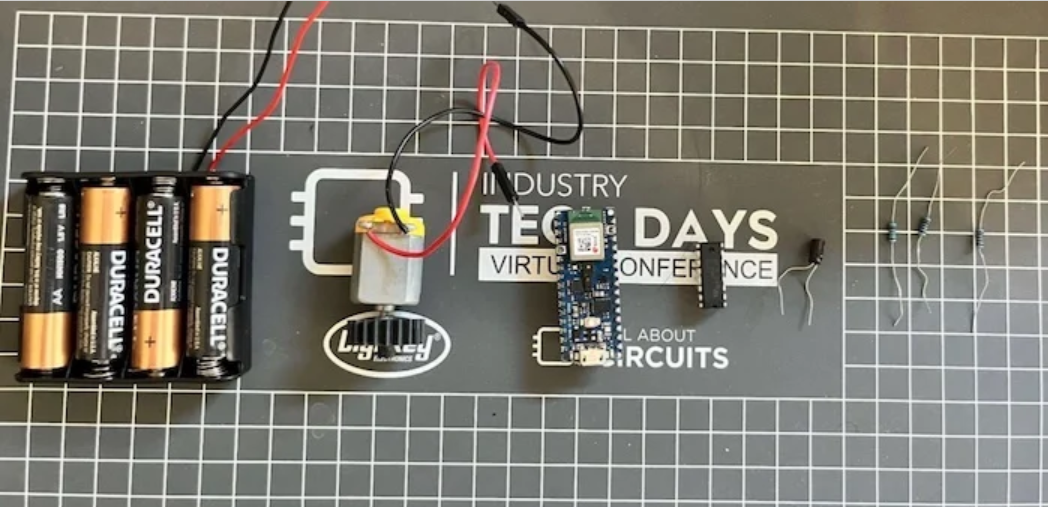
Table 1 outlines the materials needed for this project.
|
Part |
Example |
Cost (USD) |
Notes |
|
Arduino Nano 33 BLE Sense |
Link |
$22.50 |
This is a standard TinyML development device. |
|
L293D Dual H-Bridge Motor Driver |
Link |
$4.50 |
Using this IC since I had it available. You can choose any H-bridge. |
|
DC Motor |
Link |
$1.95 |
A DC motor from the Elegoo Uno R3 kit will work; any inexpensive 5 VDC motor is suitable. |
|
3x 1k Resistor |
|
$0.30 |
|
|
4x AA Battery and Connector |
Link |
$0.58 |
The input voltage can range from 4.5 to 21 V; I used 4x AA batteries (~6 V). Other power sources within this range will also work. |
(*Note: All costs are from September 2021)
For this project, I chose most components from my existing inventory.
To run TinyML scripts on our Arduino Nano 33 BLE Sense, we need to install some packages and dependencies. If you haven't already, download the Arduino IDE. After installation, you'll need to install the board files for the Arduino Nano 33 BLE Sense. In the IDE, navigate to Tools → Board → Boards Manager, search for “mbed nano,” and install “Arduino Mbed OS Nano Boards.”
Next, install the necessary libraries by going to Tools → Manage Libraries, then search for and download:
· Arduino_TensorFlowLite
· Harvard_TinyMLx
With that done, we can begin the project!
Typically, an ML workflow starts with collecting and labeling a dataset, followed by designing a model architecture. For simplicity, we'll leverage pre-existing datasets and a pre-trained keyword spotting model developed by Pete Warden. We will use Google Colab scripts provided by the TinyML team at Harvard.
You can find the necessary Google Colab here. Make sure to use a GPU runtime in your Colab (as shown) to speed up training time. Once set up, simply run each cell sequentially.
We will use the tiny_conv model architecture and train it for a total of 15,000 steps, with the first 12,000 steps at a learning rate of 0.001, and the last 3,000 steps at 0.0001. The model will be trained to recognize “forwards” and “backwards,” as included in Warden’s dataset.
Training may take a few hours, so ensure your computer is plugged in and has a stable internet connection.
Once training is complete, you will reach the quantization step in Colab. First, we freeze our model, consolidating all relevant training results into a single file for inference. Next, we convert the model into a TFLite format. The process is straightforward using the scripts provided by Harvard, and the resulting TFLite model should be fully quantized and under 20 kB in size.
Colab will offer scripts to compare accuracy between quantized and unquantized models. If everything went well, their accuracies should be nearly identical.
You can find my full code as a reference here. Once we have a fully quantized TensorFlow Lite model, we need to deploy it to our Arduino. We will modify the existing micro_speech example found in the Arduino IDE under: Files → Examples → INCOMPATIBLE → Harvard_TinyMLx → micro_speech.
While the code may seem overwhelming, we won't need to focus on most of it. First, we replace the existing model in the micro_speech example with our new TFLite Micro model. The last cell of the Colab output should provide a long string of hexadecimal characters, which will be used in our Arduino code.
In the micro_features_model.CPP file, replace the existing hexadecimal characters with those from your Colab output. At the bottom of the Colab output, there will be a line starting with “unsigned int g_model_len,” followed by a number. Copy this number and replace the value of “const int g_model_len” in your Arduino code.
Next, update the micro_features_micro_model_settings.CPP file. Change the category labels from “yes” and “no” to “forwards” and “backward,” ensuring that you do not alter the “silence” or “unknown” labels.
At this stage, the TFLite Micro model should operate as intended. Now we need to control the motor based on the TinyML inference output. This involves modifying the arduino_command_responder.CPP file.
At the top of the file, we will add #define statements to specify which pins on the Arduino connect to the motor driver. In our project, we will use D2 for the ENABLE signal, D3 for Driver1A, and D4 for Driver2A. Be sure to set these pins as outputs using pinMode() in the RespondToCommand() function.
Then, we define our motor control function, which will accept a speed (unchanged for this project) and logic values for Driver1A and Driver2A. If Driver1A is HIGH and Driver2A is LOW, the motor spins in one direction; if reversed, it spins the opposite way.
Finally, update the command responses in the code. If the first character of the found command is “f” (indicating “Forward”), the motor will turn forward; similarly for the “Backward” command.
With the software set up, we can now construct the motor driver circuit. The BOM is listed above, and the schematic is shown below.
Using a power source between 4.5 and 21 V, we will power both the Arduino and the L293D. The wiring will connect D4 to the motor driver’s 2A input, D3 to the 1A input, and D2 to EN1,2. We will include a 1 kΩ pull-down resistor on each signal to ensure defined states, along with a 0.1 μF capacitor for decoupling.
In this project, we successfully created a small audio keyword spotting model capable of running locally on an MCU powered by standard AA batteries. I hope this project highlights the value and potential applications of TinyML.
Previous: What is an Application-Specific Integrated Circuit (ASIC)?
Next: Power Dissipation of a CMOS Inverte