
Products

Throttle position sensor (Image source)
Throttle position sensors have become more advanced as vehicles adopt new technologies like electronic throttle control (ETC) systems. These updates not only make vehicles more responsive but also help improve fuel efficiency and lower emissions.
It is therefore beneficial for both automotive professionals and enthusiasts to understand how these parts work especially TPS, the different types available and their impact on engine performance.
That’s our focus today.
This article explores the importance of TPS and its basic operation including problems and maintenance tips to keep your engine running smoothly.
A throttle position sensor (TPS) is a device that measures the throttle valve’s position in an engine. This valve controls the amount of air entering the engine. The TPS sends this information to the engine’s computer which adjusts fuel delivery and other parameters accordingly.
You can find the TPS attached to the throttle body which is part of the engine’s intake system.
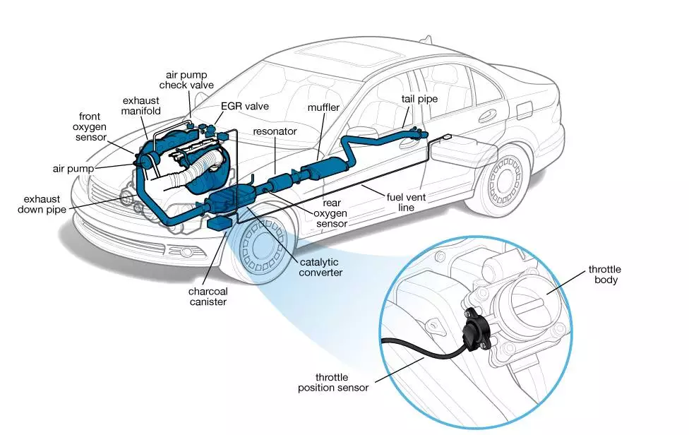
Throttle position sensor in the engine’s intake system (Image source)
There are several types of TPS each with different features and functionalities.
Potentiometric throttle position sensors are among the most commonly used types. They consist of a resistive track and a wiper that slides along the track as the throttle moves. This movement changes the resistance which in turn alters the voltage signal sent to the ECU.
The simplicity and cost effectiveness of potentiometric sensors makes them a popular choice.
For instance, if a throttle is hallway open, the wiper might be positioned in the middle of the resistive track altering the voltage proportionality. This precise measurement ensures accurate data for the ECU to manage the engine’s performance.
Hall effect throttle position uses a magnetic field to determine the throttle position. A magnetic attached to the throttle shaft changes its position relative to a hall sensor as the throttle moves. This change in position alters the magnetic field producing a varying voltage signal sent to the ECU.
This type of sensor has an advantage of no moving parts which reduces wear and tear. Hall effect throttle position sensors are also resistant to dust and other environmental factors making them suitable for harsh conditions. This durability and reliability are important for vehicles operating in diverse environments.
One can assume a situation where the hall sensor yields a voltage within a range of 0.5 V at closed throttle to 4.5 V at fully open throttle. This wide range is beneficial as it increases the ability of the system to closely monitor the throttle position so that the ECU can receive accurate data that it can use to optimally modulate the engine’s parameters.
Inductive throttle position sensors operate based on inductance, a property of electrical circuits where a change in current flow induces a voltage. These sensors feature a coil and a metal plate attached to the throttle shaft.
As the throttle moves, the position of the metal plate relative to the coil changes altering the inductance. This change is then converted into a voltage signal for the ECU.
Inductive sensors are also non-contact and highly durable. They offer excellent accuracy and are resistant to mechanical wear making them ideal for long term use.
Their high precision ensures the ECU can make fine adjustments to the engine’s performance, enhancing fuel efficiency and reducing emissions.
Contactless throttle position sensors use advanced technologies such as capacitive or optical sensing to determine throttle position. Capacitive sensors measure changes in capacitance caused by the movement of dielectric material between capacitor plates.
Optical sensors on the other hand use light and photodetectors to detect throttle movement.
Such sensors have high levels of accuracy because there’s no contact between the sensing and measured object. They are also suitable in use especially where they are to be used for a very long time and with a least need of any depanning.
The state of art sensing techniques ensures accurate detection of the throttle position and this is very vital in today’s complex engine systems.
With an overview of these major kinds of throttle position sensors, how do they function? Let’s see that below.
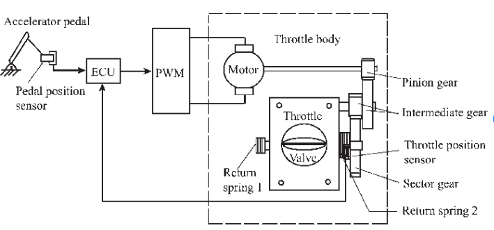
Throttle position sensor diagram (Image source)
A TPS operates through a series of steps to produce accurate measurements. Here’s a detailed breakdown of the process:
The TPS is typically mounted on the throttle body of an engine. It consists of a potentiometer and a rotor connected to the throttle shaft. When the driver presses the gas pedal, the throttle valve moves making the throttle shaft turn.
This rotation changes the position of the potentiometer’s wiper arm.
The potentiometer in the TPS is essentially a variable resistor. It has three terminals:
One is linked to a reference voltage (usually 5 V).
Another is connected to the ground.
The third is connected to the output voltage that changes with the throttle position.
The wiper arm moves along a resistive element altering the resistance between the reference voltage and ground, thus changing the output voltage.
The relationship between the throttle position and the output voltage can be represented by a simple linear equation:
Vout = Vref x Rwiper/Rtotal
Where:
Vout is the output voltage.
Vref is the reference voltage (typically 5 V).
Rwiper is the resistance between the wiper arm and the ground.
Rtotal is the total resistance of the potentiometer.
As the throttle shaft rotates, the resistance Rwiper changes. For instance, if the throttle is fully closed, the wiper is close to the ground terminal resulting in a lower output voltage.
Conversely, when the throttle is fully open, the wiper is near the reference voltage terminal resulting in higher output voltage.
To quantify this, we can consider the following example. Suppose the potentiometer has a total resistance of 10 kΩ and the reference voltage Vref is 5 V. If the throttle is at 50% open, the resistance Rwiper might be approximately 5 kΩ. The output voltage Vout can be calculated as:
Vout = 5V x 5kΩ/10kΩ
= 2.5V
This output voltage is directly proportional to the throttle position. The sensor typically operate withing a range of 0.5 V to 4.5 V, where 0.5 V corresponds to the throttle fully closed and 4.5 corresponds to the throttle fully open.
Once the TPS converts the mechanical movement into an electrical signal, this signal is sent to the ECU. The ECU is the brain of the engine management system responsible for making real time adjustments to the engine’s performance based on various inputs including the TPS signal.
Through TPS signal, the ECU is able to identify the throttle position of the motor and the required air fuel mixture. For instance, if the TPS signal shows that the throttle is opening quickly, the ECU might supply fuel to the combustion chamber to match the increased air flow to ensure maximal utilization of the fuel.
To explain how ECU interprets the TPS signal, let us consider the following case.
The TPS provides an output voltage that is used by the ECU to determine the throttle position. Suppose the TPS output voltage is 3V. Given that the TPS output range is from 0.5 V (fully closed) to 4.5 V (fully open), we can use a linear relationship to calculate the throttle percentage.
To find the throttle opening percentage for a given output voltage, let’s use this formula:
Throttle Position Percentage = (Vout – Vmin) / (Vmax – Vmin) x 100%
Where:
Vout = TPS output voltage (3 V in this case)
Vmin = Minimum output voltage (0.5 V)
Vmax = Maximum output voltage (4.5 V)
Plugging in the values:
Throttle Position Percentage = {(3 V- 0.5 V) / (4.5 V – 0.5 V)} x 100%
= {2.5 V/4.0 V} x 100%
= 0.625 V x 100%
= 62.5%
Thus, a TPS output voltage of 3 V corresponds to a throttle opening of approximately 62.5%.
The ECU uses the throttle position to adjust the air-fuel mixture. The desired air fuel ration is often 14.7:1 for optimal combustion (stoichiometric ratio). If the throttle is open at 62.5%, the ECU needs to adjust the fuel delivery accordingly.
To calculate the required fuel low, we first need to determine how the fuel flow rate changes with the throttle position. Assume the base fuel flow rate at 0% throttle is 100 cc/m. The ECU must adjust this rate proportionally to the throttle position.
Adjusted Fuel Flow Rate = Base Fuel Flow x Throttle Position Percentage / 100%
Plugging in the values:
Adjusted Fuel Flow Rate = 100 cc/min x 62.5% / 100%
= 100 cc/min x 0.625
= 62.5 cc/min
Therefore, for a throttle opening of 62.5%, the adjusted fuel flow rate is 62.5 cc/min.
The ECU continually monitors the air-fuel ratio with additional sensors such as the oxygen sensor to ensure the mixture is current. If there is a discrepancy between the actual air-fuel ratio and the desired stoichiometric ratio (14.7:1), the ECU makes real time adjustments.
Here is an example.
If the actual air-fuel ratio is detected to be 15.0:1 (indicating a lean mixture), the ECU will increase the fuel flow to correct the ratio. On the other hand, if the ratio is 14.5:1 indicating a rich mixture, the ECU will reduce the fuel flow.
This feedback mechanism ensures the engine runs efficiently optimizing performance and emissions.
The adjustment can be calculated as follows:
Determine the error in air-fuel ratio:
Desired ratio = 14.7:1
Actual ratio =15.0:1
Error = 15.0 -14.7 = 0.3
Adjust the fuel flow rate:
If the actual air-fuel ratio is lean, the ECU might increase fuel flow by a percentage proportional to the error. For instance, if a 0.3 error requires a 10% increase in fuel flow:
Increase percentage = 0.3/14.7 x 100%
= 2.04%
Therefore, if the current fuel flow rate is 62.5 cc/min:
New fuel flow rate = 62.5 cc/min x (1 + 0.0204)
= 62.5 cc/min x 1. 0204
= 63.7 cc/min
This calculation ensures that the ECU makes a precise adjustment to maintain the desired air-fuel ratio contributing to optimal engine performance and fuel efficiency.
Although TPS is important for engine performance, it can develop issues that impact vehicle functionality.
Unstable Idle: Erratic idling or stalling may occur due to incorrect throttle position data sent to the ECU.
Poor Acceleration: Hesitation or sluggish performance when pressing the accelerator can indicate a faulty TPS.
Increased Fuel Consumption: Incorrect throttle data can lead to inefficient fuel usage and higher fuel consumption.
Check Engine Light: A malfunctioning TPS can trigger the check engine light and store trouble codes in the ECU.
Diagnosing a faulty TPS involves several steps to confirm the sensor’s condition. Here’s the process:
Visual Inspection: Check for visible damage or loose connections on the TPS and wiring harness.
Scan for Trouble Codes: Use an OBD II scanner to detect any TPS related trouble codes like P0120 or P0122.
Voltage Test: Measure the TPS output with a multimeter while moving the throttle manually. Ensure the voltage changes smoothly and consistently.
Live Data Monitoring: Use a scan tool to monitor TPS data. Verify if the sensor’s output matches the throttle position accurately.
Here are the most common questions on TPS.
When a TPS sensor goes bad, it can cause erratic idling, poor acceleration and increased fuel consumption.
If your TPS is not working, the engine may experience unstable idle, hesitation and inconsistent power delivery.
The main function is to monitor the throttle valve’s position and send this information to the engine control unit for optimal air-fuel mixture and ignition timing.
Although TPSs have become more advanced with modern vehicle technologies like electronic throttle systems, they can still experience issues. A malfunctioning TPS can lead to problems such as erratic idling plus increased fuel consumption etc.
Understanding the role of TPS in regulating the air-fuel mixture is therefore important for both automotive enthusiasts and professionals.
By knowing the types, operation, and common issues together with tips for maintaining TPS, you can ensure your engine runs smoothly and effectively.
Previous: CR2032 Battery: Your Essential Guide
Next: Understanding TVS Diodes: A Guide to Transient Protection