
Products
Transient, those sudden spikes or dips in voltage or current pose a big risk to electronic circuits. These rapid fluctuations often measured in nanoseconds or milliseconds can range from a few millivolts to thousands of volts.
Even seemingly minor transients can corrupt data, while larger surges cause significant component failure.
This article explores Transient Voltage Suppressor (TVS) diodes, essential components designed to protect your circuits from these harmful events.
As briefly seen above, transients are brief disruptions in the voltage or current within a circuit. These disturbances are usually very short lasting from just a few microseconds to several milliseconds.
![]()
Now, despite their short duration, transients can spike to high levels of voltage or current. These spikes can be dangerous because they might surpass the limits that electronic devices are designed to handle.
Transients can arise from different sources both internal and external to the electrical system. Here are some primary causes:
The power grid can experience fluctuations due to load changes or switching operations. An example is when a large industrial machine is turned on where it can draw a substantial amount of power. This causes a dip followed by a spike in voltage as the grid adjusts.
The fluctuations can induce transients in connected circuits.
Electric motors especially large ones, can generate transients when starting or stopping. This is due to inrush current required to start the motor which can create a sudden spike in the circuit.
When a motor starts, the initial current can be several times higher than its normal operating current causing a sharp rise in voltage.
Inductive components are like transformers and inductors. They typically store energy in their magnetic fields. When the current through these components is suddenly interrupted, the energy can be released as the transient voltage spike.
This phenomenon known as inductive kickback occurs because a collapsing magnetic field induces a voltage opposite to the original flow.
Here is an illustrated explanation.
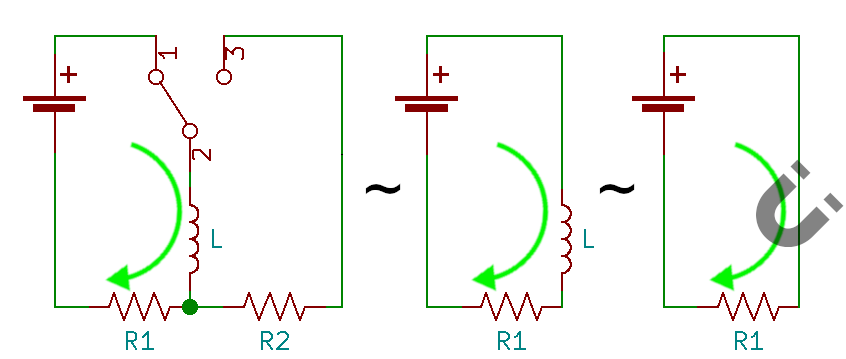
The image above illustrates the three stages of inductive kickback:
The switch (SW1) is closed and current flows through the inductor (L) and resistor (R1). The inductor stores energy in its magnetic field.
The switch is opened attempting to interrupt the current flow. However, the inductor resists this change and tries to maintain the current. This causes a collapse of the magnetic field.
The collapsing magnetic field induces the high voltage spike across the inductor with a polarity of opposite to the original current flow. This is our inductive kickback. The “ZAP!” symbol emphasizes the potential danger of this voltage spike.
In a calculation, we can consider an inductor with an inductance (L) of 10 mH carrying a current (I) of 2 A. If the current is suddenly interrupted, the voltage (V) induced across the inductor can be estimated using the formula:
Assuming the current drops to zero in 1 µs (1 × 10⁻⁶ seconds), we can calculate the voltage as follows:

Given:
Inductance (L) = 10 mH = 10 × 10⁻³ H
Change in current (dl) = 2 A
Time interval (dt) = 1 µs = 1 × 10⁻⁶ s
Substituting these values into the formula:

Calculating this gives:
10 × 10⁻³ × 2 × 106 = 20,000 V
This calculation shows that a 10 mH inductor can produce a 20,000 V transient iif the current is stopped rapidly, illustrating the potential severity of transients from inductive loads.
Transients can be categorized based on their characteristics and origins. Here are three common types:
EFTs are rapid bursts of high frequency energy often caused by switching inductive loads or relay contact bounces. EFTs can induce noise in circuits causing malfunctions in sensitive electronics.
ESD occurs when static electricity is suddenly released. For instance, touching a metal doorknob after walking on a carpet can result in a spark due to the discharge of accumulated static electricity.
In electronic circuits, ESD can damage components by creating voltage transients that exceed the components’ breakdown voltage.
To understand this better, let’s estimate the energy released during an ESD event. The energy can be calculated using the formula:

Where:
C is the capacitance (for example the typical capacitance of human body is around 100 pF)
V is the voltage difference
If we assume a voltage of 10,000 V, we can calculate the energy as follows:
Given:
Capacitance (C) = 100 pF = 100 × 10⁻¹² F
Voltage (V) = 10,000 V
Substituting these values into the formula:
E = ½ x 100 × 10⁻¹² F x (10, 000 V)2
This gives:
E = ½ x 100 × 10⁻¹² x 100, 000, 000 = 5 x 10⁻⁴ J
While the energy might seem small, it can be sufficient to damage sensitive semiconductor components.
Lightning is a natural cause of transients capable of large voltage spikes. A direct strike or even a nearby strike can induce transients in power lines, potentially reaching tens of thousands of volts.
If a lightning strike induces a transient of 100,00 V in a power line and the connected equipment is rated for a maximum of 240 V, the excess voltage can cause catastrophic failure.
Transients can have severe consequences for electronic systems. Here are some potential impacts:
When transients exceed the voltage or current ratings of electronic components, they fail. An example is a microcontroller with a maximum voltage of rating 5V which can be destroyed by a transient of 12V, leading to permanent damage.
In digital systems, transients can interfere with data signals leading to errors or corrupted data. This can manifest as system crashes, incorrect outputs or lost information.
Transients can cause unpredictable behavior in electronic systems. For example, a transient might inadvertently trigger a relay causing machinery to operate unexpectedly. This can be dangerous in industrial settings.
So, how can these voltage spikes be prevented? By using transient voltage suppressor (TVS) diodes.
A transient voltage suppression (TVS) diode is a type of semiconductor device designed to protect electronic circuits from voltage spikes: transients.
TVS diodes works by clamping excessive voltages ensuring that sensitive components are safe. Let’s see how they accomplish this through their clamping mechanism focusing on aspects like breakdown voltage to response time.
The breakdown voltage of a TVS is fundamental parameter that defines the voltage level at which the diode begins to conduct. Under normal conditions, the diode is non conductive and does not interfere with the circuit operation.
However, when the voltage exceeds the breakdown level, the diode becomes conductive diverting the excess energy away from the sensitive components.
This property is important because it ensures that the circuit remains protected only when necessary without interfering with regular operation.
Once a TVS diode starts conducting, it clamps the voltage to a maximum safe level known as the clamping voltage. This clamping action prevents the voltage from rising further, thereby protecting the downstream components from potentially destructive overvoltage conditions.
The clamping voltage is an important specification as it dictates the maximum voltage that the circuit will be exposed to during a transient event.
The peak pulse power rating indicates the maximum amount of power a TVS diode can safely dissipate during a transient event. This rating is a major indicator of the diode’s ability to handle high energy surges.
It is determined by the product of the clamping voltage and the peak current that flows through the diode during the transient.
For instance, a high peak pulse power rating means that the diode can absorb significant energy protecting the circuit from severe transients.
Also Read: The Diode Clamping Circuit
The response time of a TVS diode is another parameter reflecting how quickly the diode can respond to a voltage transient. This speed is usually in the nanosecond range allowing the diode to react almost instantly to protect the circuit.
A fast response time is important because even a brief exposure to overvoltage can cause significant damage to sensitive electronic components.
In a high speed electronic systems, the rapid response of TVS diodes ensures that the transients are clamped before they can propagate and cause damage. The quick action is essential in protecting delicate components such as microprocessors and memory devices.
Let’s understand this better with the use of an image where:
VP is the peak voltage of the transient.
VC is the clamping voltage of the TVS diode.
VBR is a reverse breakdown voltage of the TVS diode.
IC is the peak current through the TVS breakdown
VF is the forward voltage of the TVS diode.
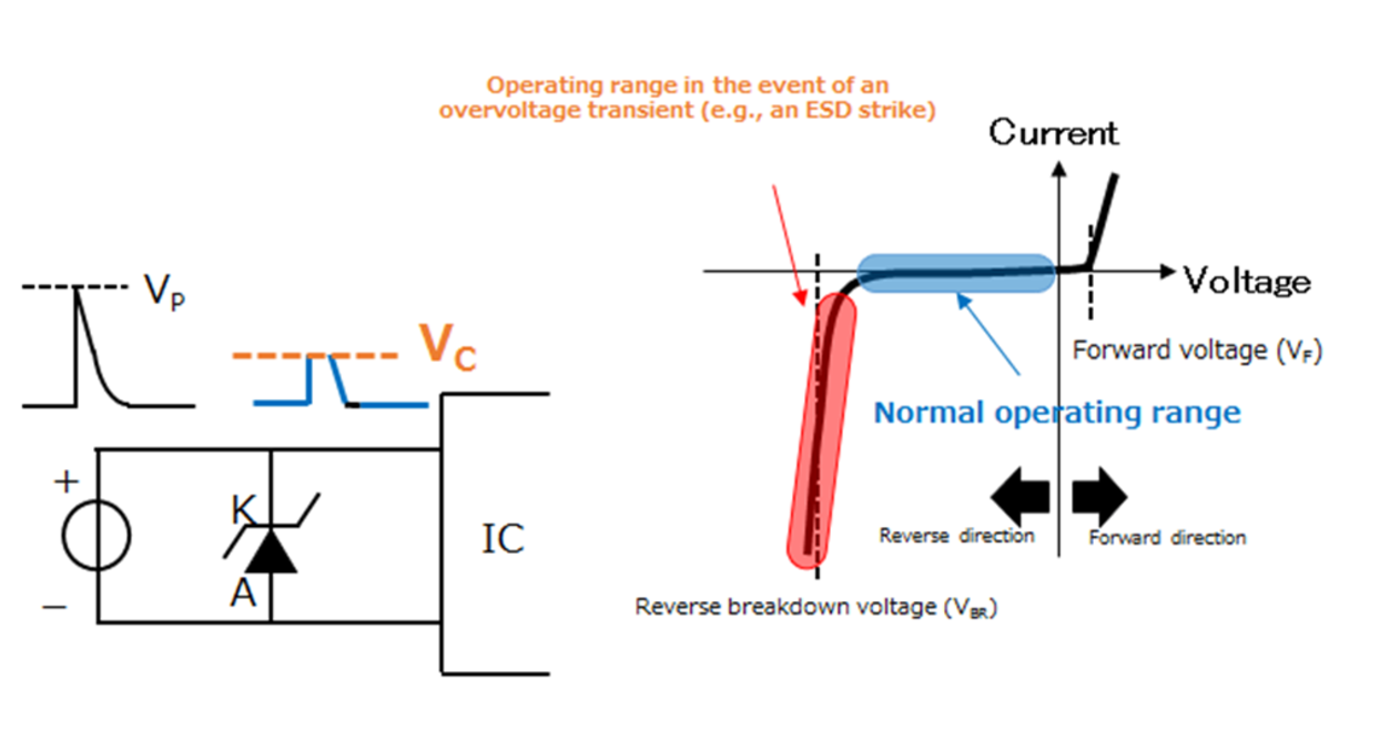
Here’s the breakdown:
Normal operation: The TVS diode is in a non-conductive state with negligible current flow.
Overvoltage Transient:
A sharp voltage spike (Vp) exceeds the TVS diode’s voltage breakdown voltage (VBR).
The TVS diode enters the breakdown region conducting a high current (IC) to clamp the voltage at the clamping voltage (Vc).
The TVS absorbs the excess energy from the transient protecting downstream components.
Graph: The I-V characteristic curve of the TVS diode shows non conductive region, the breakdown region and forward conduction region.
To make the idea even clearer, we will elaborate on a calculation example involving a TVS diode to illustrate how it protects a circuit during a transient event.
Scenario: A TVS diode is used to protect a sensitive electronic circuit. The circuit normally operates at 12 V, but it can tolerate upto 15 V without damage. A transient voltage spike reaches the circuit and we want to ensure the voltage does not exceed 15 V.
TVS Diode Specifications:
Breakdown Voltage (V<sub>BR</sub>): 14 V
Clamping Voltage (V<sub>C</sub>): 15 V
Peak Pulse Power (P<sub>PP</sub>): 1500 W
Peak Pulse Current (I<sub>PP</sub>): The current that flows through the diode during clamping
The breakdown voltage is set at 14 V. Under normal conditions, the voltage in the circuit is 12 V, so the TVS remains non conductive. When a transient event occurs and the voltage exceeds 14 V, the diode starts to conduct.
As the voltage increases, the diode clamps the voltage at its clamping voltage of 15 V. This means that even if the transient voltage tries to push the circuit higher, the diode will maintain it at 15 V.
To ensure the diode can handle the energy from the transient, we calculate the peak pulse current. The peak pulse power rating (P<sub>PP</sub>) of the diode is 1500 W.
The relationship between the clamping voltage (V<sub>C</sub>), peak pulse current (I<sub>PP</sub>), and peak pulse power (P<sub>PP</sub>) is given by:
PPP = Vc x IPP
Rearranging the formula to solve for I<sub>PP</sub>:
Ipp = Ppp/Vc
Plugging in the values:
Ipp = 1500w/15V
Ipp = 100A
Thus, the peak pulse current is 100 A. This means the TVS diode can safely handle a current of 100 A at the clamping voltage of 15 V during a transient event without being damaged.
The energy dissipated (E) during the transient can also be estimated if the duration of the transient (t) is known. For simplicity, let’s assume a transient duration of 1 millisecond (ms). The energy dissipated is:
E = PPP x t
E = 1500W x 0.001s
E = 1.5J
This calculation indicates that the TVS diode dissipates 1.5 joules of energy during the transient. The thermal management of the diode must be adequate to handle this energy dissipation without damage.
Below are some of the real-world applications of TVS diodes.
It is a stalwart in power supply circuits protecting rectifiers, filters and voltage regulators from surges.
The diode is a protective shield for automotive electronics shielding ECUs, sensors and actuators from electric spikes.
In industrial equipment, it stands as a guardian protecting motors, drives and PLCs from voltage surges caused by switching and load inrush currents.
In renewable energy systems, it protects charge controllers and batteries from the voltage spikes resulting from grid interactions.
Here are some common questions about TVS diodes.
TVS diodes are designed to regulate circuits from voltage spikes by clamping while Zener diodes regulate voltage in circuits by maintaining a constant reverse voltage.
TVS diodes are used in applications where protection from voltage transients such as ESD or lightning is needed.
This diode can fail due to excessive power dissipation exceeding its maximum voltage or current rating, or repeated exposure to transient events beyond its capacity.
In conclusion, TVS diodes are essential for protecting electronic circuits against damaging transients. By clamping excess voltage and absorbing energy surges, they protect sensitive components and ensure reliable operation.
Whether dealing with power grid fluctuations, motor switching or natural events like lightning, TVS diodes provide a solid defense making them a vital part of any electronic protection strategy.
Previous: Understanding the Role of Throttle Position Sensors in Mordren Vehicles
Next: The Basics of Schottky Diodes: A Comprehensive Guide