
Products
There may be a variety of tools on the market to help you calibrate your MCU's internal oscillator, both vendor-supplied tools and tools that run in the MCU's firmware can be used. However, to give you a more thorough understanding of the process, I recommend that you use a tool-assisted approach to correcting the MCU's internal oscillator. Assuming this is a school experiment try it at least once!
To perform this experiment, you will need a power supply, your MCU, a device programmer, a spreadsheet, and an oscilloscope, logic analyzer, or frequency meter. Here is a brief description of the steps:
1. Write and run an application program that generates a 1kHz square wave.
2. Measure the actual baseline period.
3. Measure the desired resolution of the correction register.
4. Calculate the absolute error.
5. Calculate the percent error.
6. Repeat the following steps until the desired error is achieved or no adjustment is required.
1. Calculate the necessary adjustment for the correction register.
2. Calculate the new correction value.
3. Replace the correction register value, recompile and run, then measure the new cycle.
4. Calculate the absolute error.
5. Calculate the percentage error.
Let me show an example of completing these steps on a brand new MC9S08SH8 microcontroller with the 8-bit ICSTRM register described above. According to the manual, this register has a desired correction accuracy of between ±0.2% and ±0.4%, which means that by adding or subtracting 1 step in this register, the expectation would be an increase or decrease of 0.2% to 0.4% of the baseline uncorrected period. Since this percentage will vary from chip to chip, we need to measure it.
For the purposes of this experiment, assume we want an accuracy better than ±0.5%.
1. Run a 1kHz square wave generator.
The key is to achieve an accurate 1ms period. Therefore, you should use tools provided by the MCU vendor, such as Timer or PWM modules. Use libraries and code generators and try to avoid software-based time counting delays.
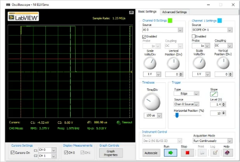
2. Measure the actual baseline cycle.
\[T_{baseline}=880.98\mu s\]
In this experiment, I used an oscilloscope from National Instruments' NI-ELVIS II suite, as shown in Fig:
3.Measure the desired resolution of the correction register.
This is typically 0.2% to 0.4% of the baseline period, or somewhere in between these values:
\[Resolution_{min}=Trim\:Accuracy_{min}\times T_{baseline}=0.002\times 880.98\mu s = 1.762\mu s\]
\[Resolution_{max}=Trim\:Accuracy_{max}\times T_{baseline}=0.004\times 880.98\mu s = 3.524\mu s\]
To make the measurements, we set ICSTRM to 129, recompiled and measured the resultant period as \(T_{baseline+1} = 883.18\mu s\). These two values show an increase in the period \(Trim\:Accuracy=0.2497\%\), which is finally calculated \(Resolution=Trim\:Accuracy\times T_{baseline}=0.002497\times 880.98\mu s = 2.2\mu s\)
4. Calculate the absolute error.
The absolute error is the difference between the obtained period and the target period. For our experiment, this error is:
\[error=T_{obtained}-T_{target}=880.98\mu s-1000\mu s=-119.02\mu s\]
A negative value means that the period obtained is shorter than the target period.
5. Calculate the percentage error.
This is simply the absolute error divided by the target period. In our experiments, it is calculated this way:
\[\% error=\frac{error}{T_{target}}=\frac{-119.02\mu s}{1,000\mu s}\times100\%=-11.9\%\]
6. Repeat the following steps until the desired error or necessary adjustment of 0 is reached.
Initially, the error is -11.9%, so we need to start iterating.
1. calculate the necessary adjustment for the correction register. This is done by increasing or decreasing the units of the correction register needed to obtain our target period. This is calculated by converting the absolute error to correction register units:
\[\Delta_{trim\_adj}=-\frac{error}{Resolution}=-\frac{-119.02\mu s}{2.2\mu s}=54.1units\approx 54units\]
We need the approximation because ICSTRM is an integer.
2. Calculate the new corrected value. \[ICSTRM=ICSTRM+\Delta_{trim\_adj}=128+54=182\]
3. replace the correction register value, recompile and run, then measure the cycle. \[T_{obtained}=1030\mu s\]
4. Calculate the absolute error. \[error=T_{obtained}-T_{target}=1030\mu s-1000\mu s=30\mu s\]
5. Calculate the percentage error. \[\%error=\frac{error}{T_{target}}=\frac{30\mu s}{1000\mu s}\times100\%=3\%\]
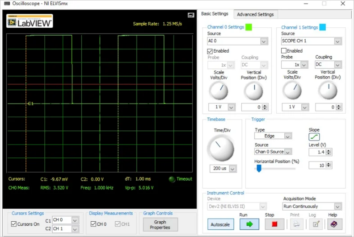
The above data only shows the results of the first iteration. After 5 iterations the error could not be further improved. The following is the output signal reported by the instrument for a 1ms period:
The following table shows the whole process:
Iteration \(TRM_{old}\) \(T_{obtained}\) Error \(TRM_{adj}\) \(TRM_{new}\) % Error
1 128 \(880.98 \mu s\) -119.02 54.10000 182 -11.90%
2 182 \(1030 \mu s\) 30.00 -13.63636 168 3.00%
3 168 \(993.39 \mu s\) -6.61 3.00455 171 -0.66%
4 171 \(999.91 \mu s\) -0.09 0.04091 171 -0.01%
5 172 \(1000.02 \mu s\) 0.02 -0.00909 172 0.002%
Note that in step 4 we reached our goal: the error dropped below 0.5%. For spreadsheets, updating the TRM value is no longer recommended, because even if it is negative. It is usually recommended to try to update the TRM value before the error rises again. So I tried to increase the TRM value in step 5, which brought the error up to 0.002%. The error is positive and the experiment is over; further improvement is not possible. For this particular chip, the ICSTRM value that should be loaded at startup will be 172.
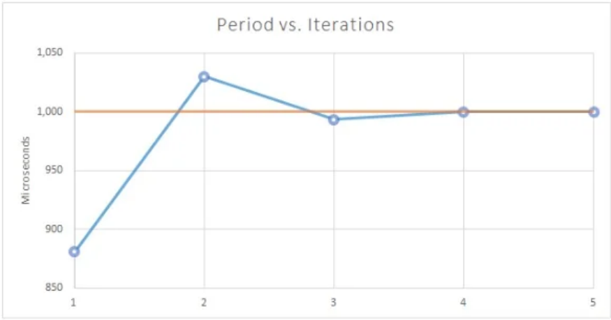
This process is almost deterministic. Looking at the error columns, you can see how much the accuracy has improved at each step: by an order of magnitude at almost every step! You can also see this improvement in the graph below.
Now that you have calibrated your MCU with a nice algorithm, remember that you don't have to run this algorithm on your microcontroller every time. You should feel free to use the tools provided by your microcontroller vendor to make the correction process easier.
Previous: Calibrating a Microcontroller's Internal Oscillator: A DIY Trimming Guide
Next: Calibrating a Microcontroller's Internal Oscillator: A DIY Trimming Guide